As you may have guessed, I completely failed to live up to my goal of reviewing everything I read, even in brief. Rather than attempting to catch up to my backlog, I am re-starting from where I am.
Yesterday I did a quick book cull by pulling books off my shelves that have been sitting there for ages, reading the first couple chapters, and deciding if I was likely to continue. I focused on books I'd started before and not gotten very far into. Here are the books that landed in the "move to Paper & Clay's used section" bag.
Trouble and Her Friends, by Melissa Scott

See the new cover? If you've been wanting to read this, it's now available as an ebook!
This is a classic lesbian cyberpunk novel that I have tried to read
at least three times, and never managed to get very far into. I kept putting it back on the shelf because it's a classic and probably objectively good, but I'm just not that into cyberpunk. If a lot of the action is taking place online, I tend to lose interest. Also, some books just don't grab me, due to a mismatch between me and the book, rather than being objectively or even subjectively bad. This is clearly one of them. Someone else can be thrilled to find it at Paper & Clay, take it home, and enjoy it.
The Splinter in the Sky, by Kemi Ashling-Garcia

A tea specialist becomes a spy in a far-future colonized world! Unfortunately, this starts with a prologue which reads much like the infamous "trade war" crawl at the top of
The Phantom Menace. Yes, I know that turned out to be prescient, but the problem was that it was written in a stultifying manner. The next couple chapters were much more lively, but also had a tendency to clunky exposition - some of which was pretty cool, to be fair. This was the second time I attempted this book, and had essentially the same reaction I did to
Trouble and Her Friends - not bad, but not for me.
Furies of Calderon, by Jim Butcher

This has been described to me as "Pokemon in alternate ancient Rome," which sounds amazing. For at least the third time, it failed to grab me. I got about four chapters in and there's still no Pokemon. Someone else will like it more than me.
The Hum and the Shiver, by Alex Bledsoe

A race of people called the Tufa have lived amongst normal humans in Appalachia since the beginning of time. They can see ghosts, have music-based magic, etc. This opens with a Tufa woman very very clearly based on Jessica Lynch, who was a real-life American soldier who was wounded and captured in the US/Iraq war, returning from Iraq. I found this in poor taste. The general style also got on my nerves.
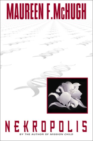
While doing this, I got sufficiently grabbed by the openings to keep reading and finish Maureen McHugh's
Nekropolis, which hopefully I will actually review. I also returned Amitav Ghosh's
Sea of Poppies and Tanya Huff's
Sing the Four Quarters to the shelf.